
PRESS RELEASE
("Kavango" or "the Company")
Preliminary Mineral Resource Estimate for
Highlights
· A preliminary JORC-compliant Mineral Resource Estimate (the "JORC MRE") totalling 33,900 ounces of gold ("oz/Au") at 2.68 grammes per tonne ("g/t") is declared at Bill's Luck, comprised of:
o 2,600 oz/Au at 3.3 g/t in the measured category.
o 13,400 oz/Au at 2.7 g/t in the indicated category.
o 18,000 oz/Au at 2.6 g/t in the inferred category.
· The resource is reported at a cut-off grade of 0.5 g/t, based on reasonable prospects for economic extraction at a gold price of
· This brings the total JORC-compliant gold resource within Hillside to 52,900 oz, building on 19,000 oz at Kavango's Nightshift project, announced
· Bill's Luck is a historic, operating gold mine that Kavango is redeveloping and re-equipping, and will support its soon-to-be commissioned 50 tonnes per day ("tpd") Carbon-In-Pulp ("CIP") plant.
· Kavango considers Hillside to be a mineralised system with significant upside potential. The Bill's Luck deposit remains open at depth and along strike, and Kavango looks forward to further upgrading the resource through targeted drilling from underground and from surface.
· Kavango's technical team will now use the JORC MRE to de-risk and accelerate development and gold production from Bill's Luck, ensuring low dilution through appropriate mining methods.
· The team is also working on the economic feasibility of small scale, trial mining pits in the unconsolidated sediments overlying the Nightshift project, to further boost gold production in a historically high gold price environment.
"At Kavango we have always believed
"The delineation of this resource paves the way for a process of longer term mine planning and efficient gold extraction to unlock further value. We are well-positioned to ramp up production and capitalise on the strong gold price environment as our CIP plant comes online."
Preliminary Resource Modelling at Bill's Luck
Gold mineralisation at Bill's Luck is structurally and hydrothermally controlled, predominantly occurring within and along the margins of these shear zones. Alteration is characterised by quartz-sericite-chlorite assemblages with disseminated sulphides, often vein-controlled and associated with syntectonic quartz-sulphide veins.
Zones of higher vein density and alteration coincide with areas of stronger deformation, with quartz boudinage, pressure shadows, and mylonitic veins serving as key mineral traps. Late stage mineralised veins also crosscut the earlier mylonitic fabric, indicating prolonged and possibly multi-phase mineralisation.
This structural complexity, combined with the presence of high-strain domains, linking shear structures, and favourable vein-hosting environments, makes the Bill's Luck area a high-potential target for structurally-controlled gold exploration within a dextral transpressional regime.
The resource drilling programme at Bill's Luck was designed to establish a maiden MRE to support and inform future mine planning and scheduling, while also unlocking the full value for what is increasingly believed to be a significant mineralised system at Bill's Luck.
The MRE utilises all data available as of
The drill programme has intersected the currently mined "Main Reef", as expected, but has also confirmed the presence of an additional "reef" structure adjacent to and parallel with the "Main Reef" that is also mineralised. The drilling also tested and intersected further "reefs" in both the hanging wall and footwall.
Highlights from the JORC MRE
Geological Data
The drilling and trenching geological, geotechnical, structural and sampling information are stored in a well-structured database system, where all documentation is readily available for validation and review.
The JORC MRE is based on the following data:
· 24 Surface diamond boreholes (6721 m).
· 35 Surface reverse circulation boreholes (4646 m).
· Geotechnical boreholes (537.7 m) - unsampled.
· 16 Percussion boreholes (1397 m) - void delineation.
· 30 Underground Diamond boreholes (1703.58 m).
· Underground mapping and sampling of exposure (192 sample channels).
· Sectional interpretation of borehole intersections using lithological, structural and sampling data.
All available data on
Assay Quality Control
A comprehensive assay quality control programme is in place, which complies with industry best practice. The results of the Quality Assurance / Quality Control programme ("QA/QC") were assessed with the following conclusions:
· Negligible sample contamination is taking place based on the results of blank material inserted in the sample batches.
· The accuracy of the results is acceptable, based on the results of the certified reference material inserted in the sample batches.
· Precision of the results is lower than would be expected. This is ascribed to the low grade and nuggety nature of the gold mineralisation, and recommendations will be made to improve this.
Geological Interpretation
Analysis of the results from regional traverse mapping, exploration-scale structural mapping and detailed core-logging showed that the gold mineralisation at the Hillside prospects associates with shear zones that have acted as fluid conduits and controlled the alteration, vein density and gold mineralisation.
At Bill's Luck, gold mineralisation occurs in steeply NNE-dipping anastomosing shear zones, and the intrusive contact between the metasedimentary rocks and the Balmoral mafic intrusives.
In the shear zones, gold is associated with smoky quartz veins that parallel shear zone foliation as well as the alteration halos of the veins. Gold also occurs in the contact zone between the metasedimentary rocks and the Balmoral mafic intrusives, where gold is hosted by smoky veins as well as the metasedimentary and the mafic rocks adjacent to the veins.
In both cases, gold-bearing veins occasionally carry sulphides (pyrite and chalcopyrite). Alteration types related to gold mineralisation are mostly silicification, sericitization and occasional chloritization. Gold deposition broadly synchronises with the early stages of the main shearing event.
The shear zones exposed and sampled underground, and intersected in boreholes were modelled in three dimensions, using geological description and structural measurements to guide the correlation or ore zones.
The main ore zone appears to comprise three en-echelon quartz vein filled shears, offset from each other by 10s of metres.
A number of sub parallel hanging and footwall zones exist, with generally lower grade gold mineralisation, associated with the metasedimentary contacts in some cases.
Deposit Dimensions and Spatial Control
Borehole positions are surveyed by differential GPS by a qualified surveyor. Down hole surveys are undertaken. A high-resolution drone survey provides topographical control. The current underground workings have been surveyed by a qualified surveyor. Historical workings a have been surveyed by drone borne LIDAR where possible.
The deposit comprises set of shear zones striking WNW-ESE and dipping at 70-80 degrees to the NNE, with a total strike of 450 m. The mineralised shears outcrop on surface, but have been extensively mined down to approximately 50 m below surface. The deposit has been shown to extend a further 150 m to depth, with the deepest intersection at 200 m below surface.
Estimation and Modelling Techniques
Estimation was done using Surpac Vision version 6.1.3 software.
A block model with parent block sizes of 12.5 m x 12.5 m x 0.8 m (y: strike, z: height, x: width) was created, and sub-blocked to 1.5 m x 1.5 m x 0.1 m to represent the volume as accurately as possible.
The individual shear zones were used as discrete geological domains, and each domain was estimated separately, using only the samples from within that zone, to prevent grade smearing between mineralised zones. The maximum projection distance used was 25 m.
Block grade estimation was done using multiple indicator kriging, a non-linear geostatistical method for estimating resources in deposits with highly skewed and mixed-grade distributions, often used in gold deposits.
Block estimates were validated visually on plan and section by comparing them to the informing sample data, as well as statistically by comparing the averages of the informing composites to the block estimates, for each shear zone.
The figures below show the results of the estimation. Black dots represent the position of borehole intersections or underground channel samples used in the estimate.
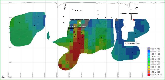
Figure 1: Bill's Luck Gold Block Grade Estimates (g/t) - Perspective View Looking NNE (HW and FW zones excluded)
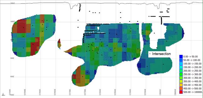
Figure 2: Bill's Luck Thickness Estimates (cm) - Perspective View Looking NNE (HW and FW zones excluded)
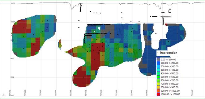
Figure 3: Bill's Luck Gold Content Estimates (cm g/t) - Perspective View Looking NNE (HW and FW zones excluded)
Mining and Metallurgical Assumptions
The deposit will be mined by underground methods.
Resources are reported at a marginal cutoff grade of 0.5 g/t, which is calculated using a gold price of
Historical Mining
Bill's Luck was originally mined between 1916 and 1950. Mining was from three shafts namely West Shaft, Main shaft and Roscor shaft.
The following areas were removed from the resource block model to account for prior mining.
· All surveyed workings on surface and underground.
· All remnant areas above 2 level (996 m elevation) at Main Shaft and Roscor Shaft.
· All remnant areas above 1 Level (2020 m elevation) at West Shaft
· All areas within 10m of the LIDAR surveyed stoped areas.
Bulk Density Determination
Dry bulk density was determined using the Archimedes Method on a large number of samples throughout the deposit. The average dry bulk density is 2.80 tonnes per metres cubed.
Resource Classification
The resource was classified into confidence classifications based on the following criteria:
· Measured Resource: Areas within the densely sampled mine workings, and adjacent areas with a borehole intersection spacing of 15 m or less were classified as measured resource.
· Indicated Resource: Blocks within 25 m from a borehole intersection, being within the resource drilling and grid were classified as indicated resource.
· Inferred Resource: Blocks between 25 and 50 m from a datapoint, as well as areas extrapolated along strike or down dip were classified as inferred resource. Hanging wall and foot wall zones with too few intersections to verify continuity were also classified as inferred resource.
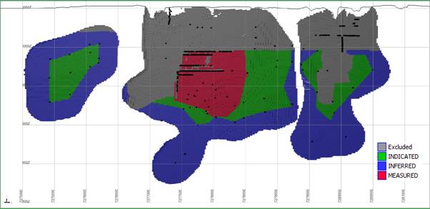
Figure 4: Resource Classification. View looking NNE (HW and FW zones not depicted). Excluded and mined out areas are shown in grey.
Bill's Luck Mineral Resource Estimate
The effective date of the Bill's Luck Resource is
|
Resource Classification |
Volume |
Tonnes |
Au g/t |
Contained Oz |
Bulk Density |
|
MEASURED |
9,000 |
24,000 |
3.30 |
2,600 |
2.8 |
|
INDICATED |
55,000 |
154,000 |
2.70 |
13,400 |
2.8 |
|
INFERRED |
77,000 |
215,000 |
2.60 |
18,000 |
2.78 |
|
|
|
|
|
|
|
|
Grand Total |
141,000 |
393,000 |
2.68 |
33,900 |
2.79 |
Notes :
1. Resources are reported in accordance with the JORC Code (2012).
2. Resources are reported at a cutoff grade of 0.5g/t, based on reasonable prospects for eventual economic extraction at a gold price of
3. Rounding as required by reporting guidelines may result in apparent summation differences between tonnes, grade and contained metal content.
4. 'Contained Oz' refers to gold in situ, actual gold recovered will likely be less than this amount
Conclusion and recommendations
The exploration drilling, logging and sampling have been done to a high standard, sufficient to support a resource estimate.
The gold mineralisation at the Bill's Luck underground workings has been demonstrated to be continuous to depth, with the potential to increase the resources through further exploration.
Kavango's Mining Strategy at Hillside
Kavango is executing a strategy of increasing gold production in
Kavango will commission its first modern CIP plant, throughput capacity 50 tpd, at Hillside in Q1 2026. The Company intends to feed the 50 tpd plant with a combination of ore mined by Kavango from the Bill's Luck underground operation, and the Hillside contractor-mined sands.
Following publication of the preliminary JORC MRE at Bill's Luck, plus the Nightshift resource, Kavango is evaluating an increase in processing capacity at Bill's Luck.
Further information in respect of the Company and its business interests is provided on the Company's website at www.kavangoresources.com and on X at @KavangoRes.
For further information, please contact:
+44 (0) 797 381 8125
Damon Heath
+44 204 530 6926
BlytheRay (Financial PR)
Megan Ray/Said Izagaren
Tel: +44 207 138 3204
(Sponsoring Broker - Zimbabwe)
Lloyd Mlotshwa
Kavango Competent Person Statement
Steve Savage
The maiden resource for Bill's Luck was prepared by Mr Stephen John Savage from S. J. Savage Consulting CC. Mr Savage is a geologist with a BSc (Hons) and M(Eng) from the
Dave Catterall
The technical information contained in this announcement pertaining to geology and exploration have been compiled by Mr David Catterall, a Competent Person and a member of a
JORC Section 1 Sampling Techniques and Data
(Criteria in this section apply to all succeeding sections.)
|
Criteria |
JORC Code Explanation |
Commentary |
|
Sampling techniques |
· Nature and quality of sampling (e.g. cut channels. random chips. or specific specialised industry standard measurement tools appropriate to the minerals under investigation. such as down hole gamma sondes. or handheld XRF instruments. etc). These examples should not be taken as limiting the broad meaning of sampling. |
· The information in this release relates to the technical details from the Company's exploration and drilling programme at · Surface Diamond drilling (HQ & NQ) was carried out, and half core samples were taken from the entire hole. · RC Drilling was carried out using a 133mm bit. Sampling was done at a standard 1m interval. · Core was cut into two using a commercial core saw adjacent to the Ori line to produce two splits as mirror images with regards to igneous textures, sedimentary bedding where possible structural fabric. · For core, samples were taken based on geological contacts, and/or of up to approximately 1m in length. The minimum sample width is 30cm to cater for distinct quartz veins which may be diluted and obscured if 1m widths were to be maintained. · Core and RC samples were submitted for a 25g fire assay with AAS finish. to either Antech Laboratory Kwekwe, or · All samples >5g/t are repeated using a gravimetric finish. · Selected samples were sent to a check lab, ALS laboratories, Johannesburg, for referee fire assay comparison. · Kavango routinely takes pXRF readings along the core using an Olympus Vanta on Geochem 3 beam mode for 60 seconds. · Underground Channel Samples were taken perpendicular to strike, some at a standard 1m width and others respecting geological boundaries. Samples were submitted to |
|
· Include reference to measures taken to ensure sample representivity and the appropriate calibration of any measurement tools or systems used |
· All Kavango's drill and trench samples were geologically logged by suitably qualified geologists on site. · Sample representativity was ensured where possible by drilling perpendicular to structures of interest, and by the sample preparation technique in the laboratory. · Channel samples were taken perpendicular to strike across the whole exposure to ensure representivity. · The entire borehole or trench was sampled based on geological logging, with the ideal sampling interval being representative of lithology for diamond core. · Individual samples are weighed at the field camp. · Upon arrival at Performance/Antech lab, the samples are dried at +/- 105 degrees Celsius for 8 to 12 hours. · The entire sample is crushed to 100% passing 4.75mm. The crushers have inline rotary splitters that split off 500g of sample that is pulverized. · The 500g split is pulverized in a Rocklabs pot and puck pulveriser with 85% passing minus 75μm. · A standard 25g aliquot is used for Fire Assay. · Following industry best practice. a series of certified reference materials (CRM's), duplicates and blanks were included for QAQC as outlined further below. |
|
|
· Aspects of the determination of mineralisation that are Material to the Public Report. |
||
| · In cases where 'industry standard' work has been done this would be relatively simple (e.g. 'reverse circulation drilling was used to obtain 1 m samples from which 3 kg was pulverised to produce a 30 g charge for fire assay'). In other cases. more explanation may be required, such as where there is coarse gold that has inherent sampling problems. Unusual commodities or mineralisation types (e.g. submarine nodules) may warrant disclosure of detailed information. | ||
| Drilling techniques |
· Drill type (e.g. core. reverse circulation. open-hole hammer. rotary air blast. auger. Bangka. sonic. etc) and details (e.g. core diameter. triple or standard tube. depth of diamond tails. face-sampling bit or other type. whether core is oriented and if so. by what method. etc). |
· The surface diamond drill holes were drilled using a diamond drill operated by · Equity uses HQ and NQ diameter conventional core barrels. · Underground drilling uses a BQ sized bit · RC holes used a 133mm bit. |
|
Drill sample recovery |
· Method of recording and assessing core and chip sample recoveries and results assessed. |
· Core recovery was monitored closely throughout from all diamond and RC drilling programmes. · Recovery in rock was >95%. · Any voids were noted. |
|
· Measures taken to maximise sample recovery and ensure representative nature of the samples. |
· Samples prepared for assay are taken consistently from the same side of the core cutting line to avoid bias. · Geologists frequently check the core cutting procedures to ensure the core cutter splits the core correctly in half. · Core samples for assay are selected within logged geological, structural, mineralisation and alteration constraints. · Diamond drill core samples are collected from distinct geological domains with sufficient width to avoid overbias. |
|
|
· Whether a relationship exists between sample recovery and grade and whether sample bias may have occurred due to preferential loss/gain of fine/coarse material. |
· For both Diamond and RC drilling the sample recoveries was generally very good and as such it is not expected that any such bias exists. · Underground channel sampling was done at a consistent channel width and depth or the sample interval. |
|
|
Logging |
· Whether core and chip samples have been geologically and geotechnically logged to a level of detail to support appropriate Mineral Resource estimation. mining studies and metallurgical studies. |
· Kavango's Diamond drill core and RC drill chips are logged by a team of qualified geologists using predefined lithological, mineralogical, physical characteristic (colour, weathering etc.) and logging codes. · Diamond drill core was marked up on site and Geotechnical logging was completed at the rig to ensure recoveries were adequately recorded. · Lithological, structural, alteration and mineralisation are logged at camp. · The core is securely stored at the base camp. · The geologists on site follow industry best practice and standard operating procedure for logging and handling all diamond drill core and RC drill chips. · The core is photographed wet and dry. · pXRF and magnetic susceptibility data are routinely captured from Diamond drill core and RC drill chips, every 0.5m to 1m. · Density measurements for drill core were determined by Archimedes density measurements i.e. using a precision balance to weigh sample in air and in submerged in water. A representative piece of core was selected from each sample for density measurement. · The QA/QC compilation of all logging results are stored and backed up on a data cloud. |
|
· Whether logging is qualitative or quantitative in nature. Core (or costean. channel. etc) photography. |
· All logging is conducted in accordance with Kavango's SOP and standard published logging charts and classification for grain size, abundance, colour and lithologies to maintain a qualitative and semi-quantitative standard based on visual estimation. · Magnetic susceptibility readings are also taken every metre and/or half metre using a ZH Instruments SM-20/SM-30 reader. · All core drilled was photographed wet and dry according to industry best practice. · All RC drill chips have a portion retained in chip trays for follow=up work and to maintain a representative sample. |
|
|
· The total length and percentage of the relevant intersections logged. |
· 100% of all recovered intervals are geologically logged. |
|
|
Sub-sampling techniques and sample preparation |
· If core. whether cut or sawn and whether quarter. half or all cores taken. |
· Selected diamond core intervals are cut in half with a commercial core cutter. using a 2mm thick blade · One half is sampled for analysis while the other half is kept for reference. · Some of the retained half core is submitted for metallurgical test work. · For selected petrographic samples core is quartered. · |
|
· For all sample types. the nature. quality and appropriateness of the sample preparation techniques |
· Field sample handling and preparation is suitable for all drilling methods utilised. · The laboratory sample preparation technique is considered appropriate and suitable for the core samples and as well as for the expected grades. |
|
|
· Quality control procedures adopted for all sub-sampling stages to maximise representivity of samples. |
· Kavango's standard field QAQC procedures for drilling samples include the field insertion of blanks, an appropriate selection of standards, field duplicates, replicates, and selection of requested laboratory pulp and coarse crush duplicates. · These are being inserted at a rate of 2.5- 5% each to ensure an appropriate rate of QAQC. |
|
|
· Measures taken to ensure that the sampling is representative of the in-situ material collected. including for instance results for field duplicate/second-half sampling. |
· Sampling is deemed appropriate for the type of survey and equipment used. · Quarter diamond core duplicates are occasionally submitted to help with understanding gold distribution and nugget effect. This could potentially bias the sample due to the nugget effect and vein hosted nature of the mineralisation and would reduce the sample volume. However, for resource calculations the quarter cores results are recombined to give an averaged result. · Trench samples are split by cone and quartering to produce field duplicates. The two results are averaged for resource estimation purposes. · Laboratory duplicates are produced from the crushed and milled core. |
|
|
· Whether sample sizes are appropriate to the grain size of the material being sampled. |
· On occasions gold from this project may be coarse, therefore, some nugget effect is expected. This is minimised by using the largest diameter of core possible with the available equipment, and by utilising halved rather than quartered core for assay. |
|
|
Quality of assay data and laboratory tests |
· The nature. quality and appropriateness of the assaying and laboratory procedures used and whether the technique is considered partial or total. |
· A company audit was made of the assay laboratory in this case · The digest and fire assay technique provide a total analysis method. · Between 5% and 20% of submitted samples consisted of additional blank, duplicate (lab duplicate from splitting the pulp), and standard samples. · Round robin and accreditation results for the laboratory were reviewed and considered acceptable. · The company's QAQC samples, including standards, are considered to confirm acceptable bias and precision with no contamination issues identified. |
|
· For geophysical tools. spectrometers. handheld XRF instruments. etc. the parameters used in determining the analysis including instrument make and model. reading times. calibrations factors applied and their derivation. etc. · Nature of quality control procedures adopted (e.g. standards. blanks. duplicates. external laboratory checks) and whether acceptable levels of accuracy (i.e. lack of bias) and precision have been established. |
· Kavango use ZH Instruments SM20 and SM30 magnetic susceptibility meters for measuring magnetic susceptibilities and readings are randomly repeated to ensure reproducibility and consistency of the data. · An Olympus Vanta C-series pXRF instrument is used in 3-beam geochemical mode with reading times of 60 seconds in total. Measurements are taken on clean dry core. · For the pXRF results no user factor was applied as per Kavango's SOP. The units are calibrated daily with their respective calibration disks. · In the case of multiple pXRF the data will be collated and user factors calculated to ascertain their effectiveness. · All QAQC samples were reviewed for precision and accuracy. Results were deemed repeatable and representative: · For pXRF appropriate certified reference materials are inserted on a ratio of 1:25 samples. · Repeat readings are taken every 25 samples. and blank samples are inserted every 25 samples. · QAQC samples are reviewed for consistency. · pXRF CRM values show a slight positive bias. including for Cu. · At low levels (<10ppm) silver values in particular are scattered. · When laboratory assay results are received blank, standard, and duplicate values are reviewed to monitor lab performance. · Select low, moderate and high-grade assay samples are selected, re-labelled and re-submitted to Performance to assess repeatability. · Select low, moderate and high-grade assay samples will also be sent for check analysis at an internationally accredited laboratory. |
|
|
|
· · · Kavango is aware of this and carries out exhaustive QAQC checks and works with Performance to ensure accuracy and repeatability. · A series of samples, including one entire hole from twinned pair have been sent to Performance in · Further external referee laboratory checks will be carried out as and when sufficient holes have been drilled to warrant. |
|
|
Verification of sampling and assaying |
· The verification of significant intersections by either independent or alternative company personnel. |
· All drill core intersections were verified by peer review. · The Company's internal CP reviewed sampling and has visited site and the laboratory to verify protocols. · Assay data was received as assay certificates and cross checked by an independent CP against sample submission data to ensure a correct match. |
|
· The use of twinned holes. |
· No twinned hole drilling has been carried out. |
|
|
· Documentation of primary data. data entry procedures. data verification. data storage (physical and electronic) protocols. |
· All data is electronically stored with peer review of data processing and modelling. · Data entry procedures standardized in SOP data checking and verification routine. · Data storage is on a cloud storage facility with access controls and automatic backups. |
|
|
· Discuss any adjustment to assay data. |
· No adjustments were made to assay data. |
|
|
Location of data points |
· Accuracy and quality of surveys used to locate drill holes (collar and down-hole surveys). trenches. mine workings and other locations used in Mineral Resource estimation. |
· Kavango's surface drill collar coordinates are captured by using handheld Garmin GPS and verified by a second handheld Garmin GPS. · Drill holes are routinely re-surveyed with differential DGPS at regular intervals to ensure sub-metre accuracy as and when sufficient holes warrant. · Downhole surveys of drill holes were done using an AXIS Champ Mag tool or the Champ Gyro (for DTH). · Underground workings and underground collar positions are surveyed by a qualified mine surveyor. · Underground voids are surveyed where possible by a drone borne LIDAR survey. |
|
· Specification of the grid system used. |
· The grid system used is UTM 35S Arc 1950. All reported coordinates are referenced to this grid. |
|
|
· Quality and adequacy of topographic control. |
· Topographic control is done by a high resolution drone survey. |
|
|
Data spacing and distribution |
· Data spacing for reporting of Exploration Results. · Whether the data spacing. and distribution is sufficient to establish the degree of geological and grade continuity appropriate for the Mineral Resource and Ore Reserve estimation procedure(s) and classifications applied. |
· Data spacing and distribution of all survey types is deemed appropriate for the type of survey and equipment used. · The drilling programmes are designed to target the multiple interpreted parallel auriferous veins at the Bill's Luck Prospect Claims. · |
|
· Whether sample compositing has been applied. |
· No composite samples have been done |
|
|
Orientation of data in relation to geological structure |
· Whether the orientation of sampling achieves unbiased sampling of possible structures and the extent to which this is known. considering the deposit type. |
· Hole orientation is designed to intersect the target structures as perpendicular as is practical. · This is considered appropriate for the geological setting and for the known mineralisation styles. · Modelling is done in 3 dimensions to model the true orientation of the structures in space. |
|
· If the relationship between the drilling orientation and the orientation of key mineralised structures is considered to have introduced a sampling bias. this should be assessed and reported if material. |
· Existence, and orientation of preferentially mineralised structures is not yet fully understood but current available data indicates mineralisation occurs within steep. sub-vertical structures, with the possibility of plunging "ore-shoots". · The drillholes are inclined towards the target, which is understood to dip towards the drillhole at a steep angle (actual geometry to be confirmed by a second hole on section in the future). · The relatively short sample length (typically 1 m) allows for relatively accurate localization of mineralisation. · No significant sampling bias is therefore expected. |
|
|
Sample security |
· The measures taken to ensure sample security. |
· Diamond core and trench samples are stored at a secure facility at the field office. · Sample bags are logged, tagged, double bagged and sealed in plastic bags stored at the field office. · Samples are stored in a locked company compound at site and in a locked container in Bulawayo. They are shipped onwards to the analytical facility by a reliable commercial courier. · Sample security includes a chain-of-custody procedure that consists of filling out sample submittal forms that are sent to the laboratory with sample shipments to make certain that all samples are received by the laboratory. · Prepared samples are transported to the analytical laboratory in sealed bags that are accompanied by appropriate paperwork. including the original sample preparation request numbers and chain-of-custody forms. |
|
Audits or reviews |
· The results of any audits or reviews of sampling techniques and data. |
· The CP has visited both site and considered practices and SOPs at both as acceptable. · The CP reviewed all data and spot-checked significant values versus certificates. |
JORC Section 2 Reporting of Exploration Results
(Criteria listed in the preceding section also apply to this section.)
|
Criteria |
JORC Code Explanation |
Commentary |
|
Mineral tenement and land tenure status |
· Type. reference name/number. location and ownership including agreements or material issues with third parties such as joint ventures. partnerships. overriding royalties. native title interests. historical sites. wilderness or national park and environmental settings. · The security of the tenure held at the time of reporting along with any known impediments to obtaining a licence to operate in the area. |
· · Kavango entered into an option agreement with the vendors, dated · This was exercised on · Leopard North remains subject to a call option valid to · Transfer of the Claims is presently underway. · More details are provided here https://polaris.brighterir.com/public/kavango_resources_plc/news/rns/story/w9nq44r |
|
Exploration done by other parties |
· Acknowledgment and appraisal of exploration by other parties. |
· The project contains a historic high-grade mine Bills Luck, which has a history of intermittent gold production from 1916 to 1950, yielding 17,000 oz at an average grade of 7.7g/t. After 1950, the mine saw only small-scale sand retreatment and surface workings. · It is currently being mined by artisanal miners, who are under contract, milling the ore at Bill's Luck stamp mill. |
|
Geology |
· Deposit type. geological setting and style of mineralisation. |
· Bills Luck lies near the southern contact of the Filabusi gold belt and the Bulawayan Basement Schists. Younger intrusive granites bound it to the north. · Gold mineralisation appears to be associated with multiple sub parallel quartz veins that occur in fine grained massive, sheared granite. · The general azimuth of the auriferous veins is 110o TN (dipping steeply to the NNE) · Bills Luck, which has a history of intermittent gold production from 1916 to 1950, yielding 17,000 oz at an average grade of 7.7g/t. After 1950, the mine saw only small-scale sand retreatment and surface workings. |
|
Drill hole Information |
· A summary of all information material to the understanding of the exploration results including a tabulation of the following information for all Material drill holes: · easting and northing of the drill hole collar · elevation or RL (Reduced Level - elevation above sea level in metres) of the drill hole collar · dip and azimuth of the hole · down hole length and interception depth · hole length. · If the exclusion of this information is justified on the basis that the information is not Material, and this exclusion does not detract from the understanding of the report. the Competent Person should clearly explain why this is the case. |
· N/A Exploration Results Not Reported |
|
Data aggregation methods |
· In reporting Exploration Results. weighting averaging techniques. maximum and/or minimum grade truncations (e.g. cutting of high grades) and cut-off grades are usually Material and should be stated. · Where aggregate intercepts incorporate short lengths of high-grade results and longer lengths of low-grade results. the procedure used for such aggregation should be stated and some typical examples of such aggregations should be shown in detail. · The assumptions used for any reporting of metal equivalent values should be clearly stated. |
· N/A Exploration Results Not Reported |
|
Relationship between mineralisation widths and intercept lengths |
· These relationships are particularly important in the reporting of Exploration Results. · If the geometry of the mineralisation with respect to the drill hole angle is known. its nature should be reported. · If it is not known and only the down hole lengths are reported. there should be a clear statement to this effect (eg 'down hole length. true width not known'). |
· N/A Exploration Results Not Reported |
|
Diagrams |
· Appropriate maps and sections (with scales) and tabulations of intercepts should be included for any significant discovery being reported These should include. but not be limited to a plan view of drill hole collar locations and appropriate sectional views. |
· N/A Exploration Results Not Reported |
|
Balanced reporting |
· Where comprehensive reporting of all Exploration Results is not practicable. representative reporting of both low and high grades and/or widths should be practiced to avoid misleading reporting of Exploration Results. |
· N/A Exploration Results Not Reported |
|
Other substantive exploration data |
· Other exploration data. if meaningful and material. should be reported including (but not limited to): geological observations; geophysical survey results; geochemical survey results; bulk samples - size and method of treatment; metallurgical test results; bulk density. groundwater. geotechnical and rock characteristics; potential deleterious or contaminating substances. |
· N/A Exploration Results Not Reported |
JORC Section 3 Estimation and Reporting of Mineral Resources
(Criteria listed in section 1, and where relevant in section 2, also apply to this section.)
|
Criteria |
JORC Code Explanation |
Commentary |
|
|
Database integrity |
· Measures taken to ensure that data has not been corrupted by, for example, transcription or keying errors, between its initial collection and its use for Mineral Resource estimation purposes. · Data validation procedures used. |
· Data is captured directly into Excel sheets. The data is then checked by the geological manager, and an external database consultant. · The data was further validated during the resource estimation process with 100% of the sample values checked against the assay certificates. |
|
|
Site visits |
· Comment on any site visits undertaken by the Competent Person and the outcome of those visits. · If no site visits have been undertaken indicate why this is the case. |
A site visit was undertaken from the 4th to the 14th of |
|
|
Geological interpretation |
· Confidence in (or conversely, the uncertainty of ) the geological interpretation of the mineral deposit. · Nature of the data used and of any assumptions made. · The effect, if any, of alternative interpretations on Mineral Resource estimation. · The use of geology in guiding and controlling Mineral Resource estimation. · The factors affecting continuity both of grade and geology. |
The mineral resource estimate is based on the following data: • 24 Surface diamond boreholes (6721m) • 35 Surface reverse circulation boreholes (4646m). • Geotechnical boreholes (537.7m) - unsampled • 16 Percussion boreholes (1397m) - void delineation • 30 Underground Diamond boreholes (1703.58m) • Underground mapping and sampling of exposure (192 sample channels). • Sectional interpretation of borehole intersections using lithological, structural and sampling data. All available data on the 30h The shear zones exposed and sampled underground, and intersected in boreholes were modelled in three dimensions, using geological description and structural measurements to guide the correlation or ore zones. The main ore zone appears to comprise three en-echelon quartz vein filled shears, offset from each other by 10s of metres. A number of sub parallel hanging and footwall zones exist, with generally lower grade gold mineralisation, associated with the metasedimentary contacts in some cases. |
|
|
Dimensions |
· The extent and variability of the Mineral Resource expressed as length (along strike or otherwise), plan width, and depth below surface to the upper and lower limits of the Mineral Resource. |
The deposit comprises set of shear zones striking WNW-ESE and dipping at 70-80 degrees to the NNE, with a total strike of 450m. The mineralised shears outcrop on surface, but have been extensively mined down to approximately 50m below surface. The deposit has been shown to extend a further 150m to depth, with the deepest intersection at 200m below surface. |
|
|
Estimation and modelling techniques |
· The nature and appropriateness of the estimation technique(s) applied and key assumptions, including treatment of extreme grade values, domaining, interpolation parameters and maximum distance of extrapolation from data points. If a computer assisted estimation method was chosen include a description of computer software and parameters used. · The availability of check estimates, previous estimates and/or mine production records and whether the Mineral Resource estimate takes appropriate account of such data. · The assumptions made regarding recovery of by-products. · Estimation of deleterious elements or other non-grade variables of economic significance (eg sulphur for acid mine drainage characterisation). · In the case of block model interpolation, the block size in relation to the average sample spacing and the search employed. · Any assumptions behind modelling of selective mining units. · Any assumptions about correlation between variables. · Description of how the geological interpretation was used to control the resource estimates. · Discussion of basis for using or not using grade cutting or capping. · The process of validation, the checking process used, the comparison of model data to drill hole data, and use of reconciliation data if available. |
Estimation was done using Surpac Vision version 6.1.3 software. A block model with parent block sizes of 12.5m x 12.5m x 0.8m (y: strike, z: height, x: width) was created, and sub-blocked to 1.5m x 1.5m x 0.1m to represent the volume as accurately as possible. The individual shear zones were used as discrete geological domains, and each domain was estimated separately, using only the samples from within that zone, to prevent grade smearing between mineralised zones. The maximum projection distance used was 25m. Block grade estimation was done using multiple indicator kriging, a non-linear geostatistical method for estimating resources in deposits with highly skewed and mixed-grade distributions, often used in gold deposits. Block estimates were validated visually on plan and section by comparing them to the informing sample data, as well as statistically by comparing the averages of the informing composites to the block estimates, for each shear zone. |
|
|
Moisture |
· Whether the tonnages are estimated on a dry basis or with natural moisture, and the method of determination of the moisture content. |
Tonnages and grades are reported on a dry basis. |
|
|
Cut-off parameters |
· The basis of the adopted cut-off grade(s) or quality parameters applied. |
The marginal cut-off grade of 0.5g/t is calculated based on a gold price of |
|
|
Mining factors or assumptions |
· Assumptions made regarding possible mining methods, minimum mining dimensions and internal (or, if applicable, external) mining dilution. It is always necessary as part of the process of determining reasonable prospects for eventual economic extraction to consider potential mining methods, but the assumptions made regarding mining methods and parameters when estimating Mineral Resources may not always be rigorous. Where this is the case, this should be reported with an explanation of the basis of the mining assumptions made. |
Mining will be by underground methods. A mining dilution of 10% is assumed. |
|
|
Metallurgical factors or assumptions |
· The basis for assumptions or predictions regarding metallurgical amenability. It is always necessary as part of the process of determining reasonable prospects for eventual economic extraction to consider potential metallurgical methods, but the assumptions regarding metallurgical treatment processes and parameters made when reporting Mineral Resources may not always be rigorous. Where this is the case, this should be reported with an explanation of the basis of the metallurgical assumptions made. |
A 90% metallurgical recovery is assumed. |
|
|
Environmen-tal factors or assumptions |
· Assumptions made regarding possible waste and process residue disposal options. It is always necessary as part of the process of determining reasonable prospects for eventual economic extraction to consider the potential environmental impacts of the mining and processing operation. While at this stage the determination of potential environmental impacts, particularly for a greenfields project, may not always be well advanced, the status of early consideration of these potential environmental impacts should be reported. Where these aspects have not been considered this should be reported with an explanation of the environmental assumptions made. |
The more competent waste rock (ie diorite/granodiorite/BIF) will be useful material for crushing for various aggregate products and for use with the construction of all-weather unsealed roads. The phyllite/meta sediment waste rock which is less competent will be useful material for future tailings dam lifts and construction due to its ability to be easily 'crushed' into clay and its ability to be compacted. Suitable waste dumps where the different waste rock materials need to be stockpiled separately will need to be designed. |
|
|
Bulk density |
· Whether assumed or determined. If assumed, the basis for the assumptions. If determined, the method used, whether wet or dry, the frequency of the measurements, the nature, size and representativeness of the samples. · The bulk density for bulk material must have been measured by methods that adequately account for void spaces (vugs, porosity, etc), moisture and differences between rock and alteration zones within the deposit. · Discuss assumptions for bulk density estimates used in the evaluation process of the different materials. |
Dry bulk density was determined using Archimedes method on numerous representative core samples throughout the deposit. |
|
|
Classification |
· The basis for the classification of the Mineral Resources into varying confidence categories. · Whether appropriate account has been taken of all relevant factors (ie relative confidence in tonnage/grade estimations, reliability of input data, confidence in continuity of geology and metal values, quality, quantity and distribution of the data). · Whether the result appropriately reflects the Competent Person's view of the deposit. |
· Measured Resource: Areas within the densely sampled mine workings, and adjacent areas with a borehole intersection spacing of 15m or less were classified as measured resource. · Indicated Resource: Blocks within 25m from a borehole intersection, being within the resource drilling and grid were classified as indicated resource. · Inferred Resource: Blocks between 25 and 50m from a datapoint, as well as areas extrapolated along strike or down dip were classified as inferred resource. Hanging wall and foot wall zones with too few intersections to verify continuity were also classified as inferred resource.
|
|
|
Audits or reviews |
· The results of any audits or reviews of Mineral Resource estimates. |
No audits or reviews have been carried out as yet. |
|
|
Discussion of relative accuracy/ confidence |
· Where appropriate a statement of the relative accuracy and confidence level in the Mineral Resource estimate using an approach or procedure deemed appropriate by the Competent Person. For example, the application of statistical or geostatistical procedures to quantify the relative accuracy of the resource within stated confidence limits, or, if such an approach is not deemed appropriate, a qualitative discussion of the factors that could affect the relative accuracy and confidence of the estimate. · The statement should specify whether it relates to global or local estimates, and, if local, state the relevant tonnages, which should be relevant to technical and economic evaluation. Documentation should include assumptions made and the procedures used. · These statements of relative accuracy and confidence of the estimate should be compared with production data, where available. |
Relative accuracy and confidence is included in the resource classification where qualitative and quantitative confidence factors are used to classify the resource on a local basis. The Bill's luck mine is producing development ore, and the plant is processing artisanal sourced material, but no stope production data is available. |
|
RNS may use your IP address to confirm compliance with the terms and conditions, to analyse how you engage with the information contained in this communication, and to share such analysis on an anonymised basis with others as part of our commercial services. For further information about how RNS and the London Stock Exchange use the personal data you provide us, please see our Privacy Policy.